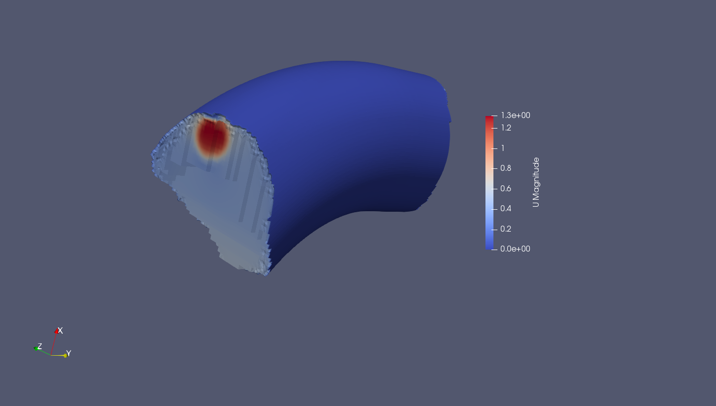

I am very curious if you get the sim to run and if there is an reasonable output. Consider the y-axe is the "gravity line".

So, basically I expect somewhat of a concentric temperature profile with increasing temperature to the center of the tank. but honestly I do not know which velocity will be established due to free convection so I am wondering about the correctness of the results itself I mean, an estimation can be done by using correlations of the kind v=f(RE, Gr, Nu), something like that but these are just estimations. The only boundary conditions which made the solver working where a velocity and pressure boundary at the inlet and outlet. Therefore I tried several boundary conditions for the inlet and oulet but all ended up in an error messsage. Originally I wanted to do a simulation without any flow - despite free convection due to temperature profile) but I recognized that with the applicable solver that is not possible (need some velocity at the inlet or outlet for initialize the velocity field).

The tank walls itself, despite inlet and outlet, are adiabatic (well insulated) and the coil wall (coil outer wall is the boundary) should have constant temperature (this is for sure a simplified model because this will not happen in real life -> temperature will increase in upward direction but for this first approach it should satisfying). It is the section of a process tank (rectangular shape) with cooling coils all arraound the tank walls. The file is attached but let me explain what I tried to simulate.


 0 kommentar(er)
